Mini Console iPod Dock Project
My gift for my Granddaughter will be a mini-console iPod dock fashioned after the stereo consoles of the mid twentieth century time frame. I have been around the block a few times deciding exactly how to structure it. I considered all kinds of options like push pull triode outputs v.s. single ended pentode/UL outputs, full range mains with integral subwoofer v.s. external sub connection etc.
In this document I intend to chronicle the progress of the design and construction.
Speakers:
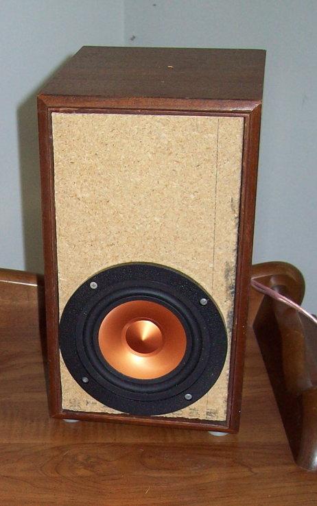
I have decided to go with the Mark Audio CHR-70 4” full range driver and supply an output for an external subwoofer. I installed the drivers in a temporary test enclosure for the purpose of break in and initial testing. The final version will be a ported enclosure of somewhat larger size so that we can get useful output down to about 40 Hz.
The preamp section will include a second order high pass filter for the mains feed to the power amp section to protect the main speakers from over excursion below the tuning frequency of the enclosure. It is likely that I will tune the enclosure to have a slight bump just above the cutoff frequency to help maintain flat response as long as possible while maintaining a steep enough roll off. The preamp will also provide a full range output that can be used with an external subwoofer amplifier. The external amplifier must provide its own low pass filtering.
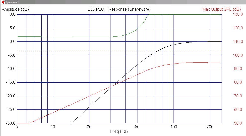
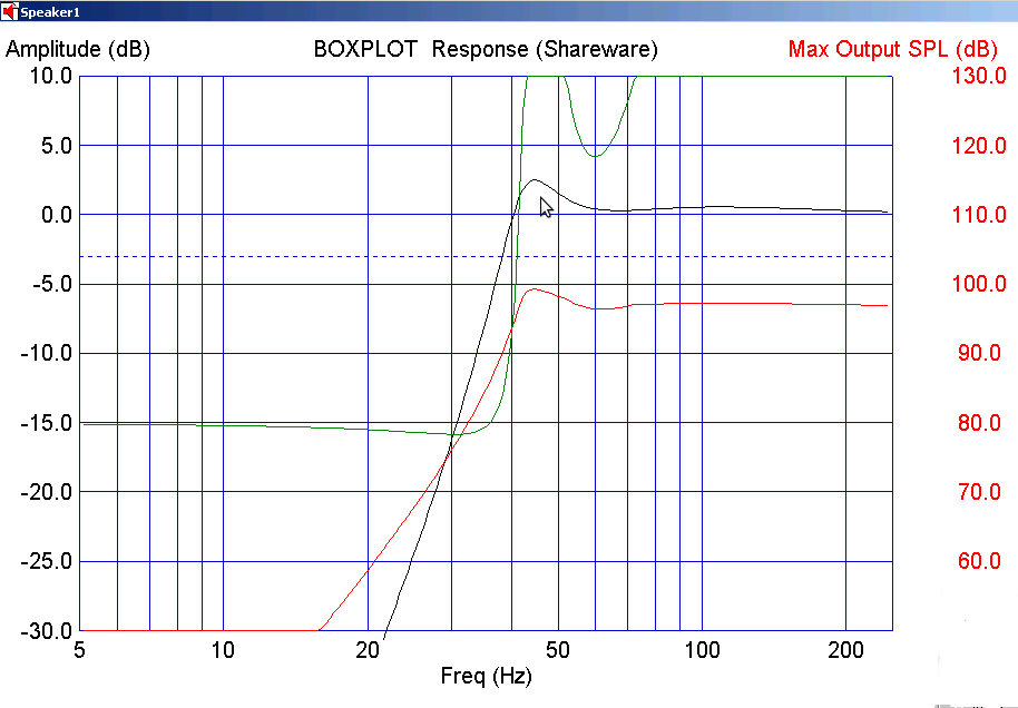
Below we compare the response simulation of a sealed alignment v.s. the ported design I am considering. In the sealed version you will note that the response is down 3dB by 80Hz and at 40Hz is down by about 12dB. Under normal circumstances one might be tempted to EQ for flat response and retain the advantages of a sealed alignment but we will be using a relatively low powered amplifier so it makes a bit more sense to go with the more efficient tuned enclosure shown next.
In the ported response you see a bump at the cut off. This intentional misalignment is designed to flatten the overall response after the high pass filter is applied.
Electronics:
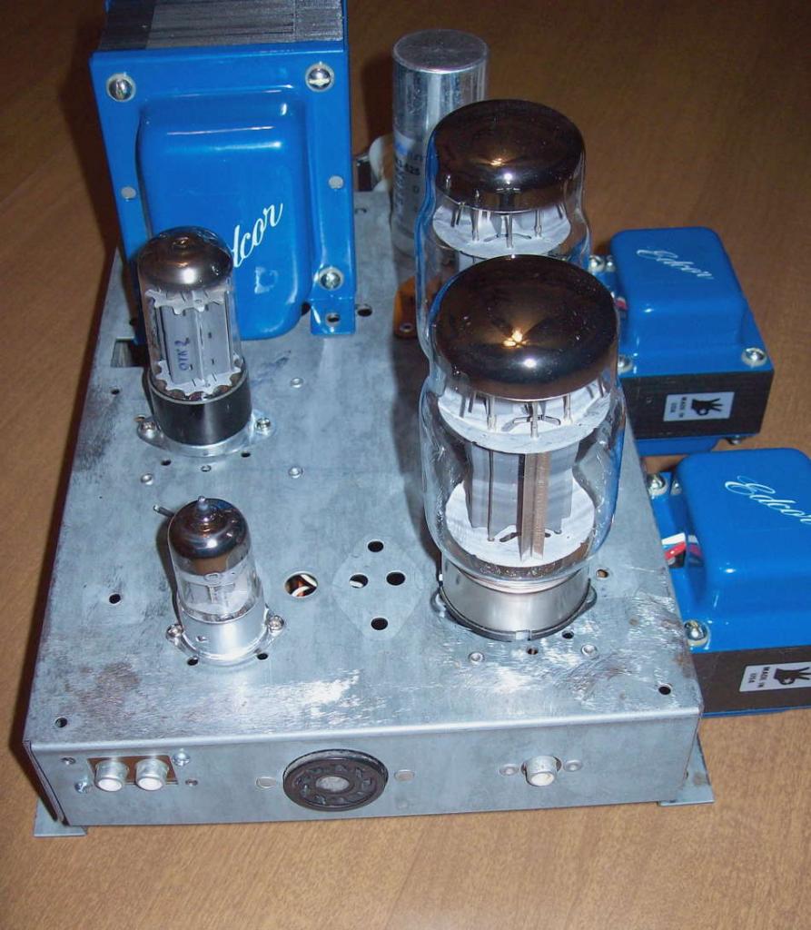
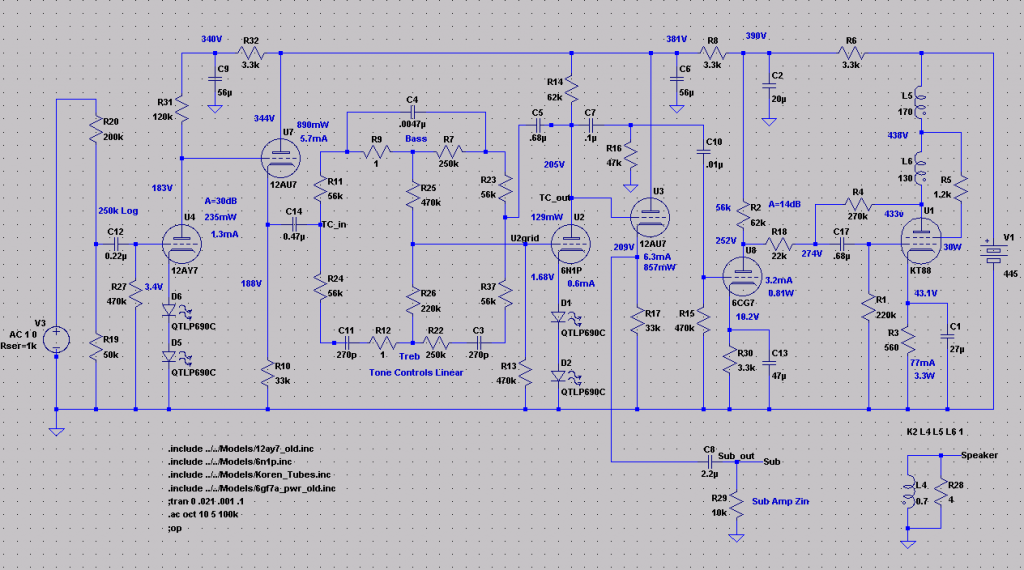
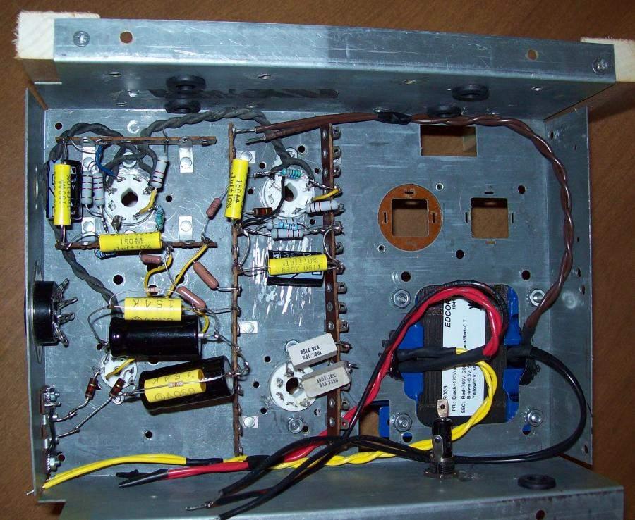
The Power Amp section is a KT-88 Single Ended Ultra-Linear with Schade feedback. I originally intended to use 6N1P as the driver but after coming up with the preamp section I realized that I did not need all the gain of the 6N1P and really would prefer to have more input voltage swing headroom so I switched to a 6CG7. I am using two separate chassis for the preamp and the Power Amp both of which were salvaged from separate electronic organs. Below you see the Power Amp chassis which I took from a solid state organ. I stripped all of the electronics and drilled it for the tube sockets. Here you see a test fitting of components. Note that the 6N1P shown is shorter than the 6CG7 that will be used in the final design.
The preamp section has a gain section followed by an active bass and treble control section after which a 2nd order high pass filter feeds the power amp and a cathode follower feeds the subwoofer output. The 22k resistor from the 6CG7 anode to the return point for the feedback is included to increase and somewhat linearize the impedance into which the feedback operates.
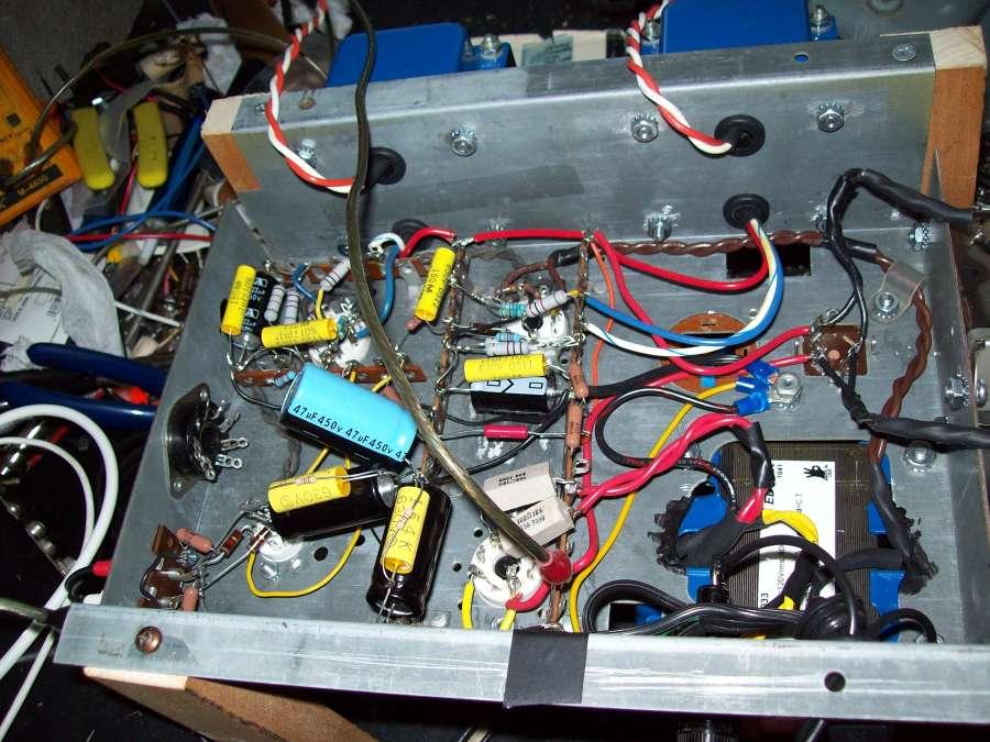
I have begun wiring up the beta test version of the power amp so we shall see how it all comes together in the real world.
I still need to add some more power supply parts and wiring but will soon be ready to test. I plan to use a little 80s vintage Radio Shack microphone mixer as a preamp. Not exactly golden ear but should allow me to determine if anything is way out of whack.
In the above picture you can see the rubber grommets used to protect the output transformer wires where they pass through the side of the chasses. The 100 ohm power resistors on the anodes of the rectifier are there to protect the modern rectifier tubes from arcing. The can cap will be in the right most cap cutout to keep it as far away from the heat as possible.
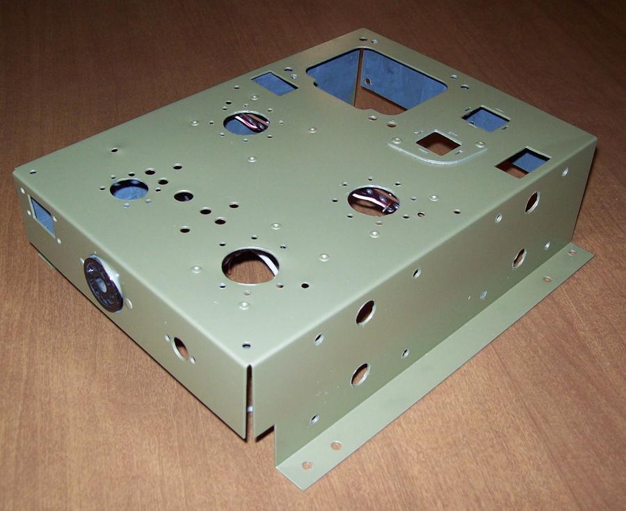
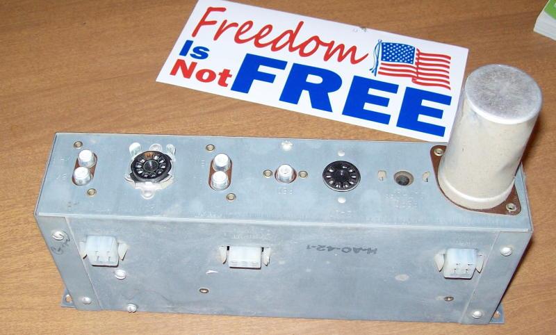
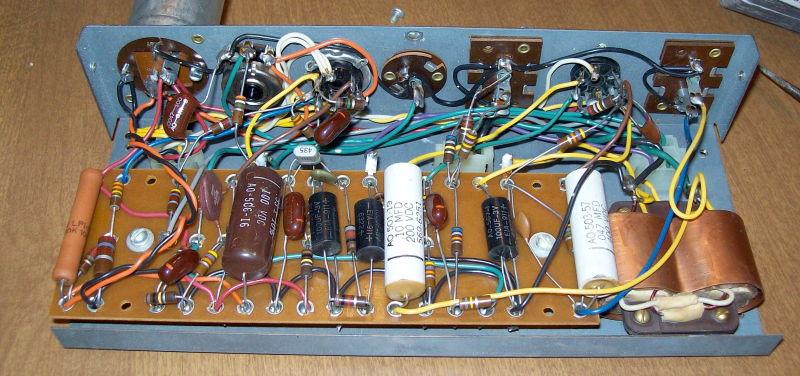
Below you can see the new paint job that I did on the chassis. I used a base coat of Rustoleum self etching primer followed by a top coat or two of metallic sage rustoleum. The preamp chassis from a Hammond tube organ is similar to the one shown below. It is the same size and shape but has a somewhat different socket layout etc.
Those two white 100 ohm power resistors on the plates of the rectifier tube were getting quite hot so I got some 50 ohm 10 watt ones (which are quite a bit larger) and replaced them. These run much cooler, though still warm, and should still provide some protection for the rectifier. The two little carbon film resistors piggybacked on the yellow and black caps are the 6CG7 bias resistors and have been replaced by 1k metal oxide versions.
When I figured that everything was hooked up right I lit her up and measured voltages while looking for traces of the magic smoke escaping. When everything appeared OK I played some music through her and it sounded pretty good given the limitations of my test setup. The speakers in my work room are some old 8 ohm tri-ax car speakers in some random sized mostly sealed enclosure. Bass was solid and midrange and treble as clear as these speakers could do.
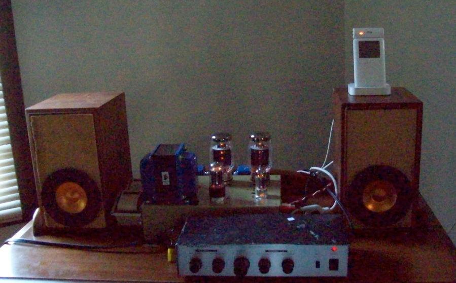
So after playing it about 4 hours and not noticing any real problems I took it downstairs and hooked it into the Mark Audio speakers in the un-optimized test boxes.
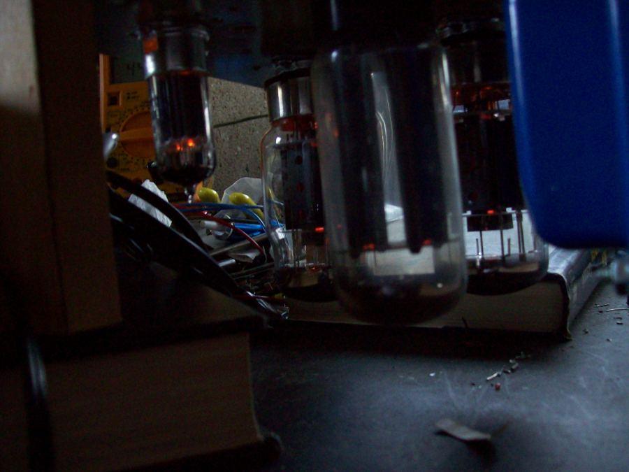
Not much bass in these little boxes but the clarity and imaging is pretty good. I apologize for the grainy picture but consumer grade point and shoot digicams can only do so much in low light and you have to see the pretty heaters glow right?
So here is some proof that it actually makes noise. :) Of course the microphone on my cheap digital camera doesn't tell you a whole lot about the quality but in person it does sound pretty good to my ears. Don't know why the imbedded player is so small. I will try to get that fixed. In the mean time if you right click (control click for mac) you can select watch on YouTube to get a full size version.


